| EMB5490 |
|
25 Apr 2010 07:28 | Quote |
Joined: 10 Feb 2008 United States  Lessons: 1 Licks: 1 Karma: 31 
|
well i soldered on a new true bypass switch and can garentee i did it right, i checked 50 times over. but i did chop off the battery snap... does that really make a difference? id never use it... should i solder it back together? |
| Phip |
|
25 Apr 2010 08:13 | Quote |
Joined: 23 Dec 2007 United States  Lessons: 1 Karma: 45  Moderator Moderator
|
Elliott. cutting off the battery clip shouldn't make a difference unless you twisted the wires together so keep looking.
Phip
|
| EMB5490 |
|
25 Apr 2010 10:40 | Quote |
Joined: 10 Feb 2008 United States  Lessons: 1 Licks: 1 Karma: 31 
|
yeah thats what i thought... its really weird... i ever just put the battery clip back on... battery doesnt work nor does the 9v input... its mad weird... |
| telecrater |
|
25 Apr 2010 11:51 | Quote |
Joined: 13 Jan 2008 United States  Lessons: 8 Karma: 13 
|
I had a problem like that with my small stone.....
I replaced the battery clip and then it stopped working...
I lay the parts on the table and it works...
I put it back in the enclosure...it does not work |
| JoshJones |
|
25 Apr 2010 12:32 | Quote |
Joined: 30 Sep 2009 United States  Karma Karma: 3 
|
telecrater, your problem is that you are shorting to ground somewhere in your encasing....
as for EMB, I would guess the same, take a multimeter and check continuity on your connections. You'll find the error pretty fast that way |
| EMB5490 |
|
25 Apr 2010 17:30 | Quote |
Joined: 10 Feb 2008 United States  Lessons: 1 Licks: 1 Karma: 31 
|
what will that do? detect faulty connections? thanks a bunch i have a feeling its my input jack, and for some reason the connection isnt solid but i cant be sure... then wouldnt it not transfer sound at all? bc it transfers the signal just not the wah |
| Phip |
|
25 Apr 2010 17:54 | Quote |
Joined: 23 Dec 2007 United States  Lessons: 1 Karma: 45  Moderator Moderator
|
if you've never worked with a multimeter this is going to be a crash course.
multimeters test for the presence of voltage (AC or DC), Amperage and resistance (ohms).
In this case Josh is refering to resistance. In some circuits you are supposed to have very low resistance and in other cases you should have high resistance (according to the engineer's design needs). A very very low resistance (0 ohms) is called a short. What Josh is suggesting is that you may have a wire that is touching the metal case of the pedal box that should NOT be touching. This would cause a short where you do not want one. That's the explanation. Now, for the practical advice. Forget the meter because you haven't used one before and make a good visual inspection. make sure you didn't cut a connection by accident by severing one of the "traces" on the circuit board. I reseached some mods for that pedal and cutting a trace is mentioned. Be sure you didn't cut (by accident) a trace close to the one you wanted to cut. when you re-assemble the box make sure no loose wires come in contact with the metal cover of the box. send me the info i requested in the PM and i'll look it over.
Phip |
| Phip |
|
25 Apr 2010 18:06 | Quote |
Joined: 23 Dec 2007 United States  Lessons: 1 Karma: 45  Moderator Moderator
|
Elliott,
The other option is to ship the thing go me UPS and i'll be happy to look it over and fix it.
Phip |
| EMB5490 |
|
25 Apr 2010 18:23 | Quote |
Joined: 10 Feb 2008 United States  Lessons: 1 Licks: 1 Karma: 31 
|
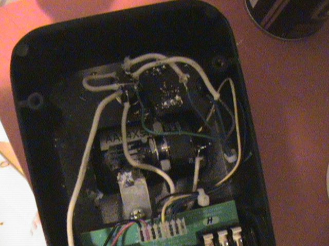
well ill take a pic of it for sure.
heres what i did or the mod i followed
http://www.stinkfoot.se/andreas/diy/mods/dunlop.htm
i added a 2.2k resistor instead of a 1.8k one i think, i made a new input wire, and of course true bypass..
theres also a whole lotta solder on the body... but ill check if a wire is touching the case.. |
| JoshJones |
|
25 Apr 2010 21:55 | Quote |
Joined: 30 Sep 2009 United States  Karma Karma: 3 
|
thanks Phip for explaining it further!
EMB clean up that solder! Good chance that your problem lies there. The solder may be touching the body. Assuming you have the green pcb, and not much solder experience, its very easy to accidentally have leads connected creating a short.
It's hard to diagnose problems such as these without actually looking at your circuit but I'd still lay odds on an accidental short. |
| EMB5490 |
|
25 Apr 2010 22:06 | Quote |
Joined: 10 Feb 2008 United States  Lessons: 1 Licks: 1 Karma: 31 
|
nope i didnt solder together two lines... that i didnt do i made sure of it. and none of the solder on the body is touching the pcb... |
| michaelcollins |
|
26 Apr 2010 00:47 | Quote |
Joined: 14 Jan 2010 United States  Licks: 1 Karma 
|
id just get a new one |
| Phip |
|
26 Apr 2010 06:36 | Quote |
Joined: 23 Dec 2007 United States  Lessons: 1 Karma: 45  Moderator Moderator
|
michaelcollins says: id just get a new one
Nah, we're gonna get that thing working better than new....you'll see!
Phip |
| EMB5490 |
|
26 Apr 2010 06:52 | Quote |
Joined: 10 Feb 2008 United States  Lessons: 1 Licks: 1 Karma: 31 
|
yep what phip said! anyway id just have to mod that crybaby. and im not about to spend over 250$ for a fulltone clyde when i can just mod one myself or make it myself. its honestly not that hard, the electronics are easy. its just the wah enclosure thats hard, and id just use my crybaby's enclosure and just swap out boards. |
| Afro_Raven |
|
26 Apr 2010 10:20 | Quote |
Joined: way back United Kingdom  Lessons: 1 Karma: 20  Moderator Moderator
|
Your crybaby doesn't work because it's been possessed by Satan himself - you lucky b*stard! |
| JoshJones |
|
26 Apr 2010 11:44 | Quote |
Joined: 30 Sep 2009 United States  Karma Karma: 3 
|
does it work outside your crybaby enclosure? |
| EMB5490 |
|
26 Apr 2010 14:08 | Quote |
Joined: 10 Feb 2008 United States  Lessons: 1 Licks: 1 Karma: 31 
|
no. |
| EMB5490 |
|
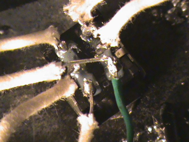
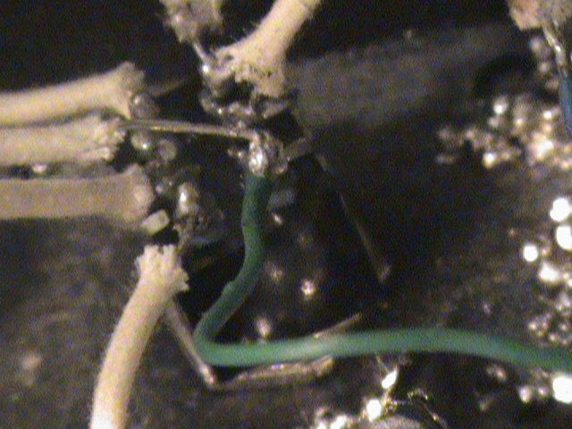
30 Apr 2010 18:21 | Quote |
Joined: 10 Feb 2008 United States  Lessons: 1 Licks: 1 Karma: 31 
|
|
| Phip |
|
30 Apr 2010 18:51 | Quote |
Joined: 23 Dec 2007 United States  Lessons: 1 Karma: 45  Moderator Moderator
|
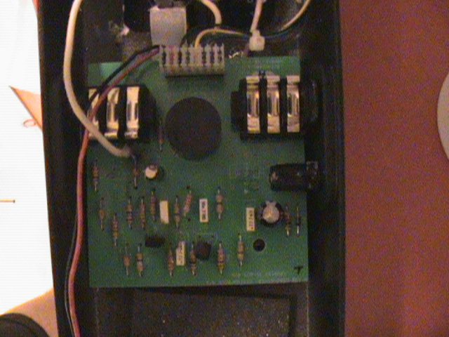
First thought, it looks like you didn't remove all the components on the board that you were supposed to remove. Did you cut the legs or did you just miss some?
more comments to come. this was my first observation and comment.
Phip |
| Phip |
|
30 Apr 2010 18:58 | Quote |
Joined: 23 Dec 2007 United States  Lessons: 1 Karma: 45  Moderator Moderator
|
I see that you removed the transistor but what about these items i marked?
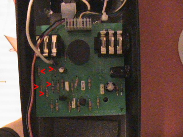
You have to remove them from the board either physically or by cutting the leads. It would be better imo to take them off completely and put them in a bag or envelope. Don't toss them out yet.
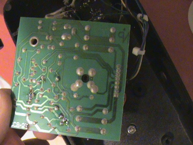
If you are having a problem with the soldrering iron then just cut the leads as close to the board as possible. Do NOT cut the trace on the back side of the board! That would not be recommended |
| EMB5490 |
|
30 Apr 2010 19:01 | Quote |
Joined: 10 Feb 2008 United States  Lessons: 1 Licks: 1 Karma: 31 
|
oh i have to??? ohhhhhhhhhhh i thought it was optional!
and of course not, theyre perfectly good resistors! ill go do tht now! easy peasy squeazey! haha |
| Phip |
|
30 Apr 2010 19:08 | Quote |
Joined: 23 Dec 2007 United States  Lessons: 1 Karma: 45  Moderator Moderator
|
It would have been optional but you removed the transistor so at that point you commited yourself to part b of the mods and the dude says it helps a bit so go ahead and get rid of those goodies
|
| Phip |
|
30 Apr 2010 19:11 | Quote |
Joined: 23 Dec 2007 United States  Lessons: 1 Karma: 45  Moderator Moderator
|
don't forget,next you will have to complete the final part of Mod2b by adding the wire in this pix.
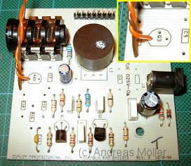
take your time and follow the instructions. (you knew that anyway)
Sterilize your tools to avoid infections! :) |
| Phip |
|
30 Apr 2010 19:25 | Quote |
Joined: 23 Dec 2007 United States  Lessons: 1 Karma: 45  Moderator Moderator
|
also i can't quite tell if you made the cut depicted in this pix.
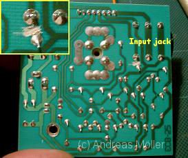 |
| EMB5490 |
|
30 Apr 2010 19:35 | Quote |
Joined: 10 Feb 2008 United States  Lessons: 1 Licks: 1 Karma: 31 
|
o *** no i didnt! good call! |
| Phip |
|
30 Apr 2010 19:40 | Quote |
Joined: 23 Dec 2007 United States  Lessons: 1 Karma: 45  Moderator Moderator
|
You can do this Elliott.......Nurse, more 3.0 solder! STAT!!!!
 |
| EMB5490 |
|
30 Apr 2010 19:48 | Quote |
Joined: 10 Feb 2008 United States  Lessons: 1 Licks: 1 Karma: 31 
|
hahah,
well ive missed cutting off the input thingy, and tommorow you gotta explain to me what the ground is and what the input is.
heres what i did,
the top rung on the left is connected to the bottom right
the middle left is to the new input
bottom left is to the 4th pic down.
top right is to blue wire to pcb
middle right is to blue wire which goes to pcb
bottom right is connected to the top left and to the green wire, which is also connected to the pcb.
did i do it right? |
| Phip |
|
30 Apr 2010 19:50 | Quote |
Joined: 23 Dec 2007 United States  Lessons: 1 Karma: 45  Moderator Moderator
|
from what i can tell.....
the wire you added in this pix shuld be removed ......
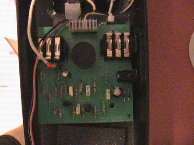
.......when you install the TWO wires in this pix.
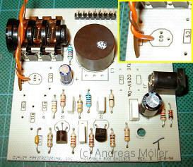 |
| Phip |
|
30 Apr 2010 19:51 | Quote |
Joined: 23 Dec 2007 United States  Lessons: 1 Karma: 45  Moderator Moderator
|
ahhh i just read your last question.....
let me study that
I'll reply soon
|
| EMB5490 |
|
30 Apr 2010 19:52 | Quote |
Joined: 10 Feb 2008 United States  Lessons: 1 Licks: 1 Karma: 31 
|
yep, and and if i understand right the orange on is to the input... then what the hell is the brown one going to?? they said to ground, but what is that and how would that be wired...
cool thanks steve :) |
| Phip |
|
30 Apr 2010 20:04 | Quote |
Joined: 23 Dec 2007 United States  Lessons: 1 Karma: 45  Moderator Moderator
|
yes sir it looks like you did that right. with one note.....
the middle left should go to the transistor's far left hole. remove the wire that you initially installed the other day (it went to the capacitor) and add the new wire from the switch to the far left transistor hole. understood?
|
| EMB5490 |
|
30 Apr 2010 20:05 | Quote |
Joined: 10 Feb 2008 United States  Lessons: 1 Licks: 1 Karma: 31 
|
uhhhhhhhhhhhhhhhhhhhhhhhhhhhhhhhhhhhhhhhh 0.0
yep i got that :) but whats that brown wire buisness? no need to worry about it or its all right? |
| Phip |
|
30 Apr 2010 20:06 | Quote |
Joined: 23 Dec 2007 United States  Lessons: 1 Karma: 45  Moderator Moderator
|
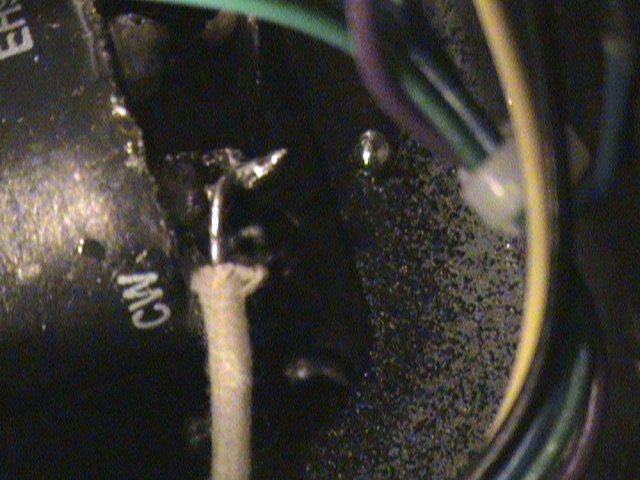
ground is the bottom left on the switch. it goes to the metal area (ground) that you mentioned in picture # 4
I quote from the mod site
"Any point that makes contact with either the pcb's ground or the wah case will work. One of the lugs on the pot has a black ground wire connected to it - you can try soldering to that point. Or draw the wire all the way back to the pcb (like the brown wire in the pic shown earlier). Anyway, this connection will short the wah input to ground in bypass mode, which more or less eliminates cross-talk and switching noise."
so to clarify the bottom left lug has to be grounded which means that a wire from that lug must be connected to the case or any "ground" connection. does that make sense to you?
|
| EMB5490 |
|
30 Apr 2010 20:08 | Quote |
Joined: 10 Feb 2008 United States  Lessons: 1 Licks: 1 Karma: 31 
|
oooh kk cool well then thats easy ill go do tht now and let you know! |
| Phip |
|
30 Apr 2010 20:11 | Quote |
Joined: 23 Dec 2007 United States  Lessons: 1 Karma: 45  Moderator Moderator
|
i'll be waiting Doc!
hmmmm "Doc Elliott"
Doctor of stringology
hahaha |
| Phip |
|
30 Apr 2010 20:18 | Quote |
Joined: 23 Dec 2007 United States  Lessons: 1 Karma: 45  Moderator Moderator
|
a side note on that brown wire issue.
it looks to me that he forgot to actually say that you should put the brown wire into the hole were the resitor was that you removed. look closely at the picture. it looks to me like he has it in the resistor hole. that hole (I downloaded the schematic) is a ground connection for the pc board. and so if the brown wire goes there (i believe it does) then the other end of the brown wire will go to the bottom left of the switch because that is also ground. and the wire you have on the bottom left now is also going to the case ground. so yeah, make sure you do that ok?
|
| Phip |
|
30 Apr 2010 20:23 | Quote |
Joined: 23 Dec 2007 United States  Lessons: 1 Karma: 45  Moderator Moderator
|
and now we wait for the results...............the tension is unbearable
|
| EMB5490 |
|
30 Apr 2010 20:26 | Quote |
Joined: 10 Feb 2008 United States  Lessons: 1 Licks: 1 Karma: 31 
|
yep ill do that in the morning.
update: IT LIVES. but sadly IT SUCKS. tone.
i odviously did something wrong, jumped something wrong here or there bc the wah effect is there whether i engage it or not, but when i turn it on it loses volume... im gona do this. i have the powerrr! |
| Phip |
|
30 Apr 2010 20:30 | Quote |
Joined: 23 Dec 2007 United States  Lessons: 1 Karma: 45  Moderator Moderator
|
well the brown wire may be the answer to that if you havent completed that connection yet. so in the morning finish the brown wire and try it again
This was fun tonight! |
| EMB5490 |
|
30 Apr 2010 21:57 | Quote |
Joined: 10 Feb 2008 United States  Lessons: 1 Licks: 1 Karma: 31 
|
yep definatly. |
|
|


